1. Introduction
My previous posts covered using an iBGP or eBGP topology in the enterprise core. This post covers the book’s third and final design where both iBGP and eBGP are used to get the best from both worlds.
2. Internal/External BGP Core Architecture
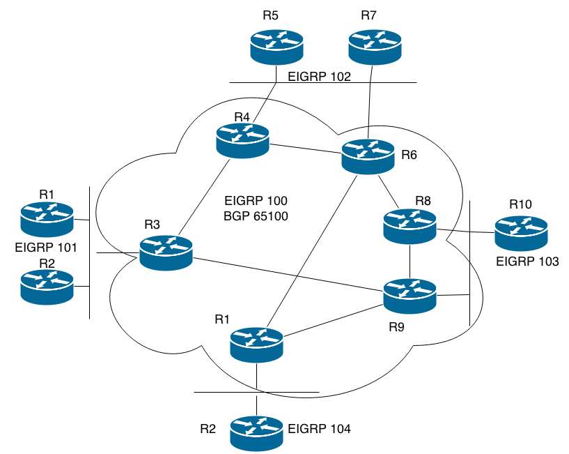
This is the diagram from the book describing the internal/external BGP design:
internal/external BGP core

As we can see, this is basically the iBGP core from the first topology connected to the regional BGP ASes from the eBGP only design. If you haven’t read the previous posts, these are the designs that I’m talking about:

The obvious question is what kind of advantages the internal/external design have over the other two. Earlier in the series we learned that the iBGP topology on the left pretty much only accomplishes one thing; reducing the number of prefixes carried in IGPs. The eBGP solution on the right solves the same prefix problem, but also makes it easier for different teams to administer the different regions.
However, the eBGP solution is less than ideal when it comes to things like path selection and convergence time after a BGP link failure. Neither solution is great for implementing BGP based inter-region traffic policy since BGP prefixes cannot be removed from any router. If one region isn’t supposed to communicate with another region, you still cannot remove those prefixes since all BGP routers may need to forward transit traffic. Instead, you have to rely on traffic filters as traffic leaves a region.
Let’s describe the moving parts in the internal/external topology, starting with the IGP processes. The core and the regions each have their own separate IGP processes and there’s no redistribution between them. The core IGP only contains the loopback interfaces of those routers and the links between them. The regional IGPs carry the prefixes used in that particular region. In the diagram and examples in the book, EIGRP is used as the IGP. This might not be the ideal IGP to use in conjunction with BGP since it doesn’t seem to have the protection against blackholes that’s provided by the IS-IS OL-bit and OSPF Max Metric Router LSA features when a router rejoins the topology. This is not addressed in this chapter of the book, but I covered it briefly in a previous post in this series.
The basic BGP configuration is an iBGP full mesh between the loopback interfaces of the core routers. The next-hop-self command is used to not have to advertise the links used for eBGP into the core IGP. Using the loopback interfaces for peering ensure that sessions stay up as long as there is some path between two routers. If there are multiple BGP routers in a regional AS, they have iBGP sessions between them as well. Prefixes are advertised into BGP on the regional BGP routers using, ideally, the network command. Alternatively, you could redistribute the IGP into BGP. A third option is to creating a summary static route pointing to null0, and then advertise that into BGP with the network command. However, that would require that the addressing plan is such that it allows summarization. Advertising a summary provides greater stability since it won’t be withdrawn from the core unless the entire region is disconnected.
3. Path Selection
When we covered the iBGP only core we learned that in an iBGP based network, with no specific policy configuration, BGP will fall back to using the IGP metric as the tie breaker. If the IGP metric is a tie, the lowest BGP router id is used if the bgp best path compare-routerid command is enabled. Normally, using the IGP metric is probably desirable since you would want your core to transport packets in the most efficient manner between regions, and the IGP metric does give some visibility into the actual underlying network. If you do not want the IGP metric to be the tie breaker, you could manually implement policy based on other higher priority BGP attributes like the local preference.
What’s new in the internal/external topology is that we have eBGP peerings between the core and the regions that, if left unattended, could result in suboptimal routing. Between R11 and R12 we really don’t have any issues since there’s only one way in and out, but let’s take a look at the multiaccess segment between AS65100 and AS 65102:

R5 and R7 advertise prefixes to R4 and R6. Similarly, R4 and R6 advertise prefixes to R5 and R7. By default, the BGP router id will be the tie breaker in the best path selection. Assuming that the router ids match the numbers on the routers, prefixes advertised by R4 and R5 will be the best paths. In other words, outgoing traffic from R4 and R6 in AS65100 will use R5 and outgoing traffic from AS65102 will use R4. This isn’t necessarily the end of the world, but traffic from AS65102 sent to AS65103 will use the path R4-R6-R8-R10 for example, instead of the shorter R6-R8-R10. Perhaps worse is that you have links on R6 and R7 that are only used unidirectionally; you can send from two interfaces in your AS, but the traffic is only received by one interface in the peers’ AS. This effectively limits your bandwidth to half of what it could be.
Default traffic flows:

You could manually solve this problem by applying incoming or outgoing policy on a per prefix or per AS basis. For example, to fix the suboptimal routing between AS65102 and 103, we could apply a policy that makes the prefixes from R6 the best paths. However, that would put us in a position to have to manually implement all kinds of policy to get the “perfect” traffic flows, introducing unnecessary complexity into the system. Instead we want a solution that’s fairly simple, and that automatically adjusts to new prefixes being added.
Two such solutions are proposed in the book. The first one is to use BGP multipath. If the BGP path selection process reaches a certain point, it’s possible to install multiple next hops in the routing table. The default number of paths is one so in this case we would have to use the maximum-paths 2 command under the bgp process. If this is implemented, traffic will be load shared by CEF which solves the link utilization issue. However, it doesn’t really fix the suboptimal routing problem that we’re having.
An alternate solution is to use the MED attribute. MED is normally associated with setting an “artificial” metric that you send to a neighboring AS in order to influence that AS’ path selection. However, it’s also possible to set the MED to the IGP metric associated with a BGP prefix. You would use the set metric-type internal command in an outgoing route map to do this. Because all ASes in this topology belong to the same enterprise, the IGP metric of another AS can be trusted to provide a valid criteria for the path selection process.
On R4 and R6 we apply the following configuration outbound:
!
route-map SET_MED permit 10
set metric-type internal
!
router bgp 65100
neighbor <ip> route-map SET_MED out
!
The result of this will be that R5 and R7 choose whether to use R4 or R6 for outbound traffic based on the destination’s IGP metric in the core. If the core links are all equal cost, traffic from AS 65102 to AS 65103 will now use the path R6-R8-R10. If we apply similar policy on R8 and R9 towards AS 65103 we will also ensure that the return traffic uses the shorter R8-R6 path instead of potentially using R9-R8-R6.
4. Remote Sites
Enterprises often have remote sites. We could imagine a retail chain with hundreds, or even thousands of remote locations. In the book, Frame Relay is used, but I the advice is probably still valid even if we now use other technologies like IPsec VPN and/or MPLS VPN. How do remote sites fit into this design? If you don’t use BGP, the remote sites would either be in the same IGP as the rest of the enterprise or connected through some kind of redistribution. If you simply implement BGP without taking remote sites into account, you could end up with the primary and backup remote site aggregation routers in different BGP ASes. This is not recommended.
According to the book, the cleanest solution is to put the routers connecting to the remote sites in a separate AS:

The remote sites and their hubs are in their own separate IGP, EIGRP 105, in BGP AS 65105. The hub routers connect directly to the core via eBGP. If the number of remote sites is large, you need to redistribute the IGP into BGP instead of using the network command. The book contains some additional discussion, like for example that you shouldn’t summarize the remote site prefixes in BGP if you have multiple hubs unless the hubs are physically connected. Doing so can create black holes.
If the router on the left in the diagram advertises a summary for all remote sites and also advertises a MED value indicating that it’s the preferred path, that summary will still be advertised even if that router loses its connection to one of the remote sites. Remember, a summary is only withdrawn if all components are lost.
This can be solved by having a physical connection between the hubs and running iBGP between them. In that case, traffic destined for a remote site could be sent over to the other hub router instead of being dropped to null0. If there is no physical connection between the hubs, it’s not recommended to run iBGP because this session would have to be set up using the remote sites as transit. In that case, it’s fine to simply advertise all remote site prefixes into the BGP core. You could also set the MED value to the IGP metric in order to direct traffic to the hub with the lowest cost to reach each particular remote site.
The chapter concludes with a case study where an enterprise is converted from using an IGP only network into a topology similar to what I’ve covered in this post.
