1. Introduction
In this post we’ll attempt to understand DMVPN phase 3, the latest and greatest enhancement to this exciting technology. In the previous post we learned how DMVPN phase 2 works and that there were certain problems with phase 2 that forced us into carrying more prefixes in the spokes’ forwarding tables than what we ideally would want. Phase 3 solves that problem.
2. Phase 3, Basics
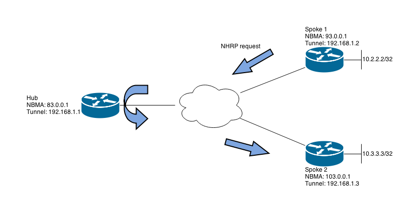
The basic idea behind phase 3 is that you do not need to maintain each spoke’s tunnel IP address as the next hop in the spokes’ routing tables. This in turn enables us to do things like summarize and use OSPF point-to-multipoint and all kinds of good things. To accomplish this we need to use a somewhat more complicated NHRP resolution request and reply system that introduces a new message, the NHRP redirect (also known as NHRP traffic indication). We’ll use the following network in this discussion:
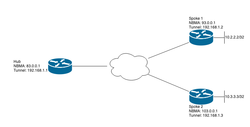
Each spoke learns the other spoke’s loopback address via a routing protocol that sets the next hop the the hub’s tunnel IP address (192.168.1.1), and this information is installed in the FIB (CEF table) as well. Now, let’s say that traffic is sent from 10.2.2.2 to 10.3.3.3. This sets in motion a process that results in the creation of a dynamic tunnel between the two spokes for those particular destinations. We’ll now walk through that process step by step. Tests done on IOS 15.2
3. Phase 3, Step by Step Explanation
1.
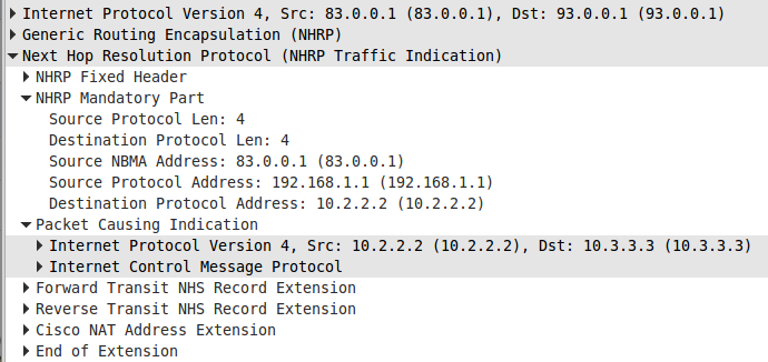
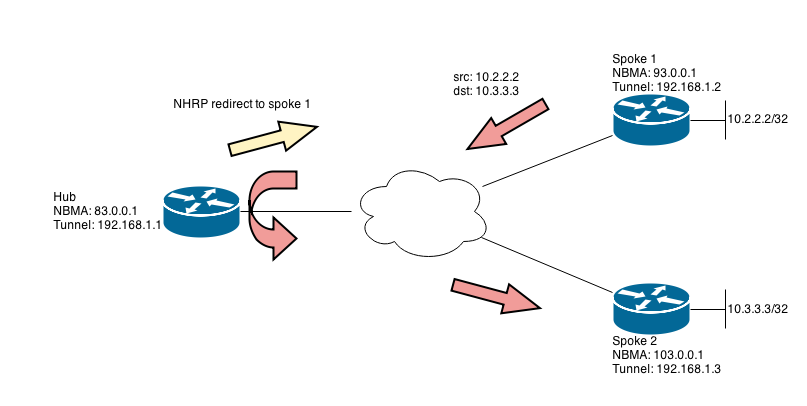
Spoke 1 sends traffic with destination 10.3.3.3 and source 10.2.2.2. The NHRP table is checked and 10.3.3.3/32 cannot be found because the dynamic tunnel isn’t established yet. Because the NHRP table doesn’t contain 10.3.3.3/32 normal forwarding has not been modified and the traffic is forwarded to the hub. The hub receives the traffic on its tunnel interface and then immediately sends it back out the same interface. The fact that the traffic is tromboned in this fashion triggers a redirect message from the hub to spoke 1. Wireshark calls this message NHRP traffic indication
2.
The important field in the redirect received from the hub is the destination, 10.3.3.3 in this case. Spoke 1 uses this information to create a NHRP resolution request containing that destination and its own tunnel and NBMA addresses (192.168.1.2 and 93.0.0.1). This request is sent to spoke 2 via the hub. The hub is able to relay the request to the correct spoke by looking at the next hop for the destination 10.3.3.3 contained in the request.
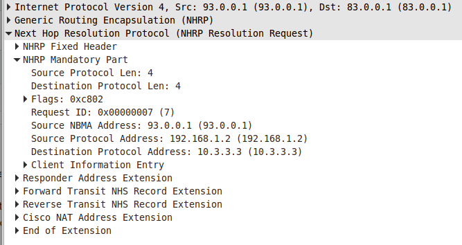
NHRP request as it’s received by the hub from spoke 1.
3.
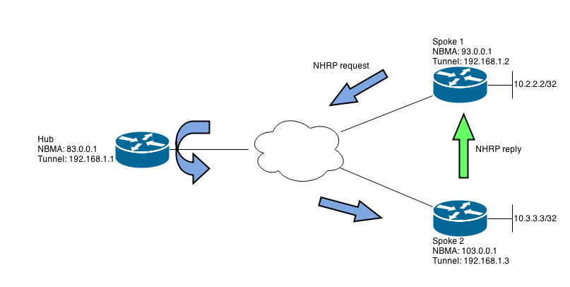
Spoke 2 extracts spoke 1’s NBMA address from the request and uses it to create an NHRP resolution reply. This reply can be sent directly to spoke 1 because spoke 2 now knows spoke 1’s NBMA address. The reply also contains the destination address 10.3.3.3 which is used to indicate to spoke 1 for which destination a dynamic tunnel can be built. Spoke 2 also uses the information in the request to build an NHRP entry for spoke 1’s tunnel IP address 192.168.1.2, mapping it to the NBMA address 93.0.0.1.
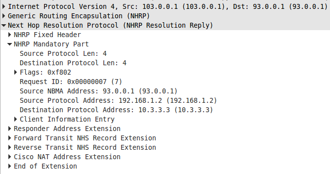
Note how the reply contains the same information as the request, but the outer header destination of 93.0.0.1 sends the packet directly to spoke 1.
4.
Spoke 1 has now received the reply from spoke 2 which verifies that spoke to spoke traffic is feasible. The destination 10.3.3.3/32 is installed in spoke 1’s NHRP table:
#show ip nhrp
10.3.3.3/32 via 192.168.1.3
Tunnel0 created 00:00:08, expire 01:59:51
Type: dynamic, Flags: router used rib nho
NBMA address: 103.0.0.1
The CEF entry for the destination is also modified:
#show ip cef 10.3.3.3
10.3.3.3/32
nexthop 192.168.1.3 Tunnel0
The routing table maintains the hub as the next hop but the percentage sign (%) indicates that this has been overridden in the actual data plane:
R2#show ip route eigrp
Codes: L – local, C – connected, S – static, R – RIP, M – mobile, B – BGP
D – EIGRP, EX – EIGRP external, O – OSPF, IA – OSPF inter area
N1 – OSPF NSSA external type 1, N2 – OSPF NSSA external type 2
E1 – OSPF external type 1, E2 – OSPF external type 2
i – IS-IS, su – IS-IS summary, L1 – IS-IS level-1, L2 – IS-IS level-2
ia – IS-IS inter area, * – candidate default, U – per-user static route
o – ODR, P – periodic downloaded static route, H – NHRP, l – LISP
+ – replicated route, % – next hop override
Gateway of last resort is 93.0.0.4 to network 0.0.0.0
10.0.0.0/32 is subnetted, 3 subnets
D 10.1.1.1 [90/27008000] via 192.168.1.1, 03:06:10, Tunnel0
D % 10.3.3.3 [90/28288000] via 192.168.1.1, 03:04:52, Tunnel0
5.
So is this it? Usually not because return traffic will typically also need to be sent. Creating the equivalent tunnel from spoke 2 to spoke 1 is a separate process, although it typically happens at the same. In this case where we originally sent an ICMP echo request to 10.3.3.3 from 10.2.2.2, an echo reply will immediately be sent from spoke 2, triggering the spoke to spoke tunnel for destination 10.2.2.2. Spoke 2 will go through the exact same process as spoke 1. Initial traffic will be sent to the hub. The hub will send the redirect back to spoke 2. Spoke 2 will create an NHRP request for the destination on spoke 1 and send it to the hub. The hub will relay it down to spoke 1 that will respond directly to spoke 2 using the NBMA address found in the request.
6.
There are some further nuances. For example, if you summarize on the hub (one of the features of phase 3 vs. phase 2 is the ability to summarize), the routing table will look slightly different. Instead of showing 10.3.3.3 with the percentage sign to indicate the overridden next hop, a new NHRP entry is installed. I’ve sent 10.0.0.0/8 from the hub to all spokes instead of the /32s
R2#show ip route
Codes: L – local, C – connected, S – static, R – RIP, M – mobile, B – BGP
D – EIGRP, EX – EIGRP external, O – OSPF, IA – OSPF inter area
N1 – OSPF NSSA external type 1, N2 – OSPF NSSA external type 2
E1 – OSPF external type 1, E2 – OSPF external type 2
i – IS-IS, su – IS-IS summary, L1 – IS-IS level-1, L2 – IS-IS level-2
ia – IS-IS inter area, * – candidate default, U – per-user static route
o – ODR, P – periodic downloaded static route, H – NHRP, l – LISP
+ – replicated route, % – next hop override
10.0.0.0/8 is variably subnetted, 3 subnets, 2 masks
D 10.0.0.0/8 [90/27008000] via 192.168.1.1, 00:03:00, Tunnel0
H 10.3.3.3/32 [250/1] via 192.168.1.3, 00:02:46, Tunnel0
This could probably be considered informational rather than serving any actual purpose because the NHRP table and the CEF table could have been modified anyway. Maintaining parity between all three tables makes sense though.
4. Configuring Phase 3
Configuration of this feature is very simple, simply enable the commands ip nhrp redirect and ip nhrp shortcut on all tunnel interfaces participating in the DMVPN. Technically, the redirect command is only required on the hub and shortcut only on the spokes, but the configuration guide recommends enabling redirect on all routers for cases when traffic takes a spoke to spoke to hub path.
If you feel that I’ve forgotten some important aspect of how these dynamic tunnels work, don’t hesitate to give me feedback.

Many thanks for such wonderful and easy to remember explanation.
Thanks so much for the clear explanation.
i appreciate for this clear explanation.
Hello,
Just one question, why you said in n°2 “The important field in the redirect received from the hub is the destination, 10.3.3.3 in this case. Spoke 1 uses this information to create a NHRP resolution request ”
The Spok 1 knows already this @ 10.3.3.3, doesn’t he ?
The reste of the steps are clear for me 🙂
Tnahks in advance
Fay
When spoke 1 sends its first packets to 10.3.3.3 it is not aware of where this destination exists, except that the next hop is the hub. Spoke 1 sends the packets to the hub and the hub sends it to the correct spoke, out the same interface as it was received. This triggers the redirect message. So far so good.
Spoke 1 then gets the redirect message from the hub, and it contains what source and destination caused the redirection. In this case that’s a packet sourced from 10.2.2.2 with the destination 10.3.3.3. You can see this in the packet capture under “Packet causing indication”. After having received this message, spoke 1 knows that 10.3.3.3 is not located at the hub, because if it was located at the hub, it wouldn’t have received a redirect.
However, spoke 1 doesn’t know anything else about 10.3.3.3. It doesn’t know spoke 2’s tunnel ip address (192.168.1.3) and NBMA address (103.0.0.1). If it already had this information, it could already build a spoke to spoke tunnel. It only knows that 10.3.3.3 is a destination for which it should build a spoke to spoke tunnel because it received a redirect message.
Spoke 1’s NHRP request in step 2 is therefore saying “I know that 10.3.3.3 is behind one of the spokes and I want to know that spoke’s tunnel/nbma addresses. I’m attaching my own tunnel/nbma addresses so that the spoke in question can answer”. This message is sent to the hub, and because the hub knows what spoke 10.3.3.3 belongs to, it can relay the message to the correct spoke.
So when I say that the important field is 10.3.3.3 I’m just referring to it being the only information spoke 1 has to go on when starting the process to build a spoke to spoke tunnel. Yes, it already knows that the prefix exists because it can send packets to it (via the hub), but not that it can build a spoke to spoke tunnel until it receives the redirect.
Excellent!!
Excellent
kindly explain little bit more about ip nhrp shortcut and redirect.
Excellent~