1. Introduction
This post is a summary of the first few sections of chapter 7 in the book BGP Design and Implementation. It covers the use of route reflectors.
2. The Basics
Route reflection is designed to solve the iBGP full mesh scalability problem. As the number of routers in an AS grows, the number of sessions between them grows exponentially, eventually reaching a number that isn’t feasible to maintain. However, not not using a full mesh in iBGP could lead to all kinds of problems like black holes and forwarding loops. If we don’t use a full mesh, some other mechanism is required to ensure that all BGP speakers receive the correct information. Route reflection is one such mechanism.
In a route reflector environment there are three types of iBGP speakers:
- Route Reflector (RR)
- Route Reflector Client
- Regular iBGP Speaker – also known as a ‘non-client’
A route reflector is essentially a normal BGP speaker that, for the most part, doesn’t need to follow the normal rule of not advertising iBGP learned prefixes to iBGP peers. However, in order to still ensure a loop free environment, additional rules and regulations are imposed on it.
A client is BGP speaker that the route reflector defines as a client. In other words, a client is unaware of its status as a client, it’s only configured on the route reflector. From the client’s perspective, the router reflector is just a normal iBGP speaker that it peers with.
A non-client is simply an iBGP speaker that the route reflector is peering with that it doesn’t define as a client.
These descriptions are from the point of few of a particular reflector; a client of one reflector can be a non-client to another, and so on. A route reflector acts as a regular iBGP speaker when peering with other RRs and non-clients.
In a nutshell, a route reflector is able to “reflect” BGP updates between routers, reducing the number of required iBGP sessions. When reflecting a route, the RR doesn’t modify most BGP attributes, like next-hop, as-path, local-pref, MED.
3. Rules For Prefix Advertisement
Let’s first define route reflection. A client sending an update and this update being re-advertised to another client (or non-client) of that route reflector is an example of reflection. As is a non-client’s update being re-advertised to a client. It’s not reflection when a RR acts as a normal BGP router. For example, sending or receiving updates to an eBGP peer.
In short:
Reflection:
client -> RR -> client
non-client -> RR -> client
client -> RR -> non-client
Not reflection:
RR -> eBGP
eBGP -> RR
eBGP -> RR -> internal peer
In other words, the RR acts as a normal BGP router in addition to its route reflection duties. This is also reflected (no pun intended) in the list of seven rules that the book uses to describe how a RR operates. Several of the rules simply describe normal BGP behaviour like advertising the best path, always advertising to eBGP peers and that a RR client acts as a normal iBGP router when it advertises to peers.
The actual RR specific rules are:
1. When receiving an update from a non-client, reflect it to all clients.
2. When receiving an update from a client, reflect it to all clients AND non-clients.
This diagram shows a basic example topology used in the book:

The middle AS would normally require N(N-1)/2 = 5(5-1)/2 = 10 sessions. By using a RR, we reduce that number to 5. Three sessions for the full mesh between R3,R4 and R5 and two sessions between the RR and its clients. Obviously, an AS that small could operate just fine with full iBGP mesh, but as the AS grows, that becomes increasingly difficult to manage.
The diagram illustrates the different rules discussed earlier. When the RR (R5) receives an update through eBGP from R8, it acts as a normal BGP speaker and re-advertises the update to all other routers with which it has a peering session. When it receives an update from its non-clients, R3 and R4, the update is reflected to the clients R6 and R7, but also advertised normally to the eBGP peer R8. An update from a client, e.g. R6, is reflected to the non-clients R3 and R4 and to the clients, R6 and R7. The RR also advertises R6’s update to R8 as per normal BGP rules.
4. Clustering
If a client peers with just one RR we have a single point of failure. In the diagram above, if R5 fails, R6 and R7 will no longer receive any BGP routing information. To avoid this single point of failure, it’s common that a client peers with multiple route reflectors. A topology might look something like this:

The client, R3, peers with both route reflectors. The RRs will peer with one another and all other RRs in the AS. The potential problem with that is that it could cause routing information loops. For example, an update from R3 is sent to both R1 and R2. R1 will reflect the update to R2 and R2 will reflect it to R1. This is normal route reflector behaviour since, from each RRs’ perspective, the other RR is a non-client. If either R1 or R2 considers the reflected update to be the “best” in the bgp best path selection, it will be reflected back to R3. This isn’t necessarily catastrophic, but it’s not ideal either because if you modify various BGP attributes in just the wrong ways, you could turn this routing information loop into a loop in the data plane. However, because BGP route reflection introduces several new attributes that are designed to prevent routing information loops, this loop wouldn’t actually occur.
The BGP cluster-id attribute breaks the loop in this topology. The cluster-id is a 4-byte value associated with every route reflector, and by default its the router’s BGP router-id. If two RRs have the same cluster-id, they reject updates from one another. In our topology we would ensure that R1 and R2 are in the same cluster by configuring matching cluster-ids. When R1 reflects the update received from its client, R3, the non-client, R2, rejects it. Other loop prevention mechanisms are covered in the next section.
5. Loop Prevention Mechanisms
The book makes a clear distinction between routing information loops and routing loops. A routing information loop is when control plane information is looped back to the router that originated the advertisement. An example would the redundant route reflection topology above where R3 could potentially receive the same update that it sent out. A routing loop (forwarding loop) on the other hand is a data plane phenomenon where an IP packet is forwarded between two or more routers without reaching the intended destination. A routing loop can happen without a routing information loop, and a routing information loop doesn’t always lead to a routing loop. If deployed incorrectly, route reflectors can lead to routing loops, but routing information loops are prevented using various attributes.
Let’s reuse the diagram from the cluster-id example:

This time, R1 and R2 are in different clusters. The client receives an update and sends it to R1 and R2. The update is then reflected between the two RRs, and if one of them has policy in place that makes the update from the other RR better than the one received directly from the client, it’s reflected to the client, creating a routing information loop. To prevent this from happening, the originator-id attribute is used. Whenever a RR receives a prefix, it sets the originator-id to the router-id of the router that sent the update. In this case, both R1 and R2 will set the originator-id to R3’s router-id as they receive the incoming update. The originator-id is not updated by subsequent RRs that might process the same update. If the update is received back in by R3, it’s rejected due to containing the router’s own router-id in the originator-id attribute.
A potential routing information loop is also present when several route reflectors in different clusters are clients of one another.

In this diagram, the route reflectors are clients of other route reflectors in order to propagate routing information. This creates the potential for routing information loops. The cluster-id cannot be used because the RRs are in different cluster (otherwise, they wouldn’t be able to send and receive information from one another). An attribute called the cluster-list is introduced instead, and it’s essentially the route reflector equivalent of the as-path based loop prevention mechanism in eBGP. Each RR prepends its own cluster-id whenever it reflects an update. If it receives an update with its own cluster-id in the cluster-list, it rejects the update.
6. Hierarchical Route Reflection
Because route reflectors act as normal iBGP speakers in relation to other reflectors, they must be fully meshed. If the BGP AS is very large with a large number of RRs, this could create the same kind of scalability problem that RRs were designed to solve in the first place. To overcome this, you can create hierarchy in the RR design, with lower level RRs being clients of other RRs. It could look something like this:
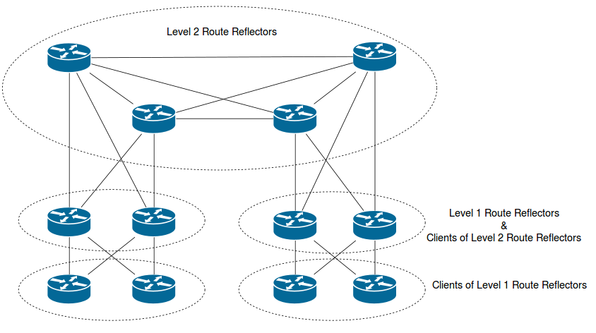
Update: That’s is the “traditional” design from the book. That’s not necessarily how you do it nowadays (read more: http://wiki.nil.com/BGP_route_reflectors)
7. Route Reflection Design
Quite a few pages in the book are devoted to explaining how you design route reflection properly. If you don’t know what you are doing, routing loops and other terrible things can happen. An interesting example can be found in this article: Anomalies in BGP: Part 1. I’m not going to cover all the examples in the book in detail because they are largely way above my level as a BGP novice, but I’m going to attempt summarize the general guidelines for how you avoid screwing route reflection up.
7.1 Align the Physical and Logical Topologies
The first rule is to keep the logical and physical topologies congruent. Ideally, you should only create a session between a route reflector and another iBGP speaker if there’s a direct connection between. That is, a session shouldn’t traverse another active iBGP router. The reason for this is that a client only has a limited view of the topology, and if two clients receive the same prefix but with different next-hops, a forwarding loop can be created. A classic example would be this design:

Instead of peering with the physically closer RR, R2 and R3’s sessions each traverse another client. If the next hop attribute isn’t modified, R2 will use R4 as the next hop for external prefixes and R3 will use R1. This will create a forwarding loop. If full mesh iBGP was used, this could still happen, but it would be much less likely and require modification of BGP attributes and/or IGP costs.
7.2 Default MED Is A Problem
If MED, with the default settings (no deterministic-med and no always-compare-med), is used in the best path selection inside an AS, route oscillation can occur. There’s a risk that prefixes are continuously advertised and withdrawn in an endless cycle. Reading the book, the exact reasons for this is a combination of the fact that router reflectors only reflect the best path and the way the MED attribute is handled in the best path selection. The exact process is a bit convoluted, but suffice to say, it’s really bad. Several options exist to fix this problem, including not using route reflection at all, using the always compare MED feature, using deterministic MED and resetting MED. The book recommends using the deterministic MED command. Deterministic MED makes it irrelevant in which order prefixes were received when MED is used in the best path selection, solving the entire problem. Resetting MED, and instead relying on community values for that type of policy is also a valid solution.
A similar oscillation problem related to IGP metrics can also occur, but because it’s also solved by using deterministic MED, I don’t see much point in writing much about it.
7.3 Clustering Design
Making incorrect choices when you do clustering can lead to traffic black holes in certain failure scenarios. Consider this design:

R2 and R3 belong to a single cluster. Some external prefix enters the AS on R4 and reaches R1 through both R2 and R3. Because R2 and R3 are in the same cluster, they don’t exchange this prefix between them. The problem with that is that if R2 or R3 loses its BGP session to R4, and R1 uses that router as transit to reach R4, traffic will be black holed. If R2 and R3 were in different clusters, the prefix would still exist on those routers even if it was no longer received directly from R4.
7.4 Resetting the Next Hop
The BGP next hop is maintained within the AS and not changed by route reflection. Most of the time, this is a good thing and helps prevent routing loops. In certain situations however, you maybe want to change the next hop as a prefix is reflected. If the RR receives the prefix from an external peer, you can use the next-hop-self command. If the prefix is learned through iBGP this is not possible and you need to use an outbound route map. You’re advised to only change the next hop if you know what you are doing since it can create forwarding loops.
